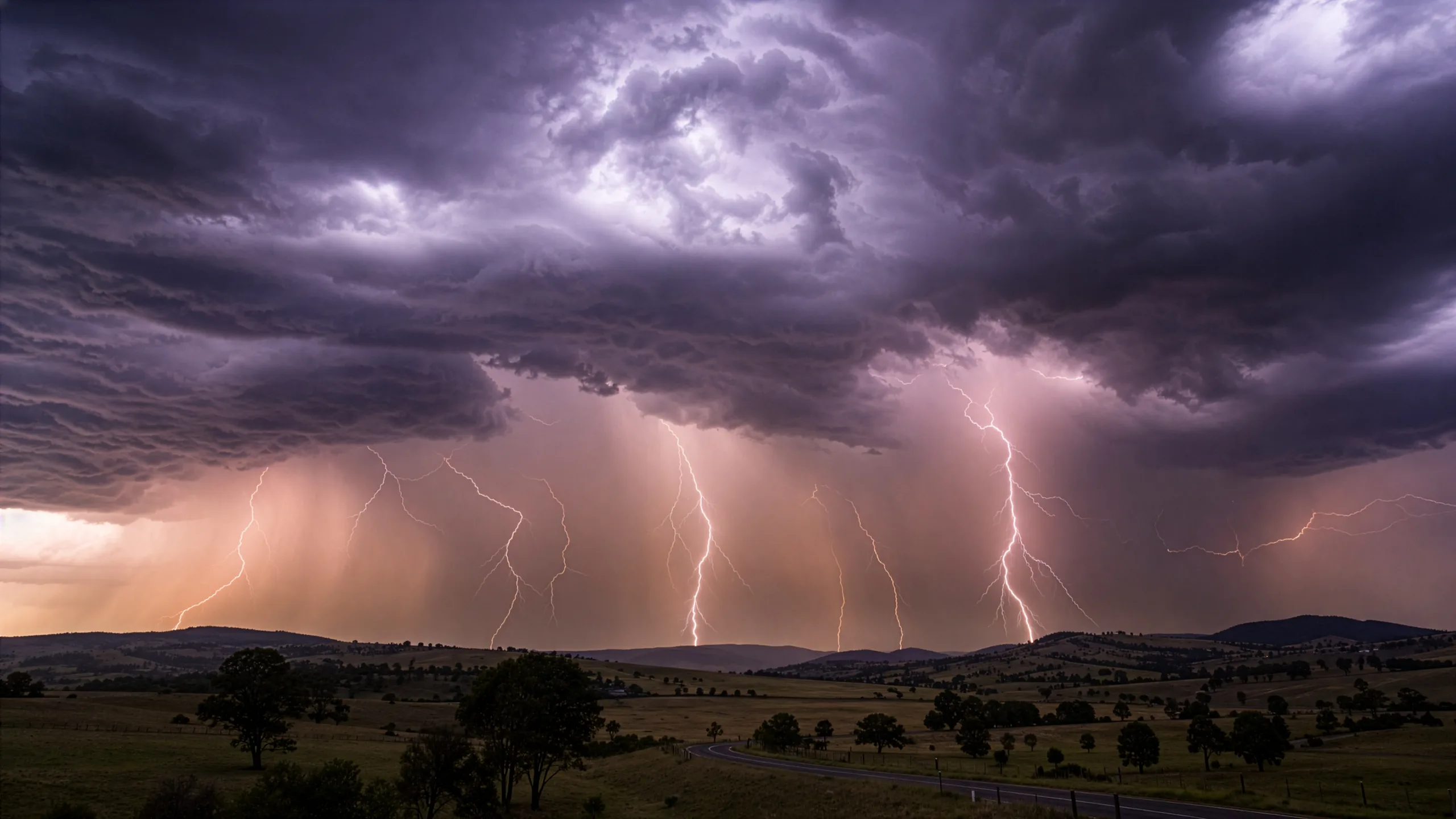
Lightning poles, sometimes called lightning masts or lightning protection poles, are substation structures built to be struck. IUP designs and supplies steel lightning poles for electrical substations and battery energy storage systems (BESS). IUP’s earlier article on substation structures noted that an effective shielding system “depends on pole height, placement, and the geometry of the equipment being protected”, all of which vary with each layout.
This article picks up from that point. Each of those variables is a decision with an owner, a governing standard and a consequence if it goes wrong. For asset managers, project developers and contractors, the sequence matters. The standards frame the shielding study. The study sets each lightning pole’s position and height. The site, the height and any lights set the structural loads. The earthing design decides where the intercepted current goes.
Which Standards Govern Lightning Protection in an Australian Substation?
Lightning protection must first conform to AS 1768:2021, while AS 2067:2016 sets the wider requirements for the substation itself. AS 2067:2016 provides minimum requirements for the design and erection of high voltage installations above 1 kV AC. Its contents include clause 6.6, “Protection against direct lightning strikes”, and Section 8, “Earthing systems”, but clause 6.6 leaves the choice of shielding method to the designer.
The Australian Government’s ABLIS listing describes AS 1768:2021 Lightning protection as covering conventional lightning protection systems, from the air termination through to earthing and surge protection, with a risk management process for assessing the risk of lightning damage. In Western Australia, the same listing records it as a code of practice under the Dangerous Goods Safety Act 2004. The current edition is an Australian Standard rather than a joint AS/NZS standard, so New Zealand projects should confirm which edition their specification calls up.
In that system, the lightning pole is the air termination. The rest of this article follows what happens to a strike once the pole has intercepted it.
What Is Changing with the Draft AS 61936.1?
AS 2067:2016 is still listed as current, but a possible replacement is in draft. In April 2026, Standards Australia opened DR AS 61936.1:2025, Electrical power installations exceeding 1 kV AC and 1.5 kV DC, for public comment until 21 April 2026, noting that “the draft may eventually replace AS 2067”.
Standards Australia said the draft “updates local content in areas such as earthing, fire risk management, and protection systems, reflecting current Australian practices”. For projects with long design programs, it is worth confirming early which document the specification calls up.
Where Does IEEE 998 Fit Alongside the Australian Standards?
IEEE 998 is commonly used alongside AS 1768 for the shielding design itself. It is an American-origin international technical guide rather than an Australian Standard, but it is a recognised reference for substation lightning shielding design in Australia.
Its 2026 edition, approved on 4 June 2026, supersedes IEEE 998-2012 and provides “design information for the methods historically and typically applied by substation designers to reduce direct lightning strokes to equipment and buswork within substations”. It presents two approaches in detail, “the classical empirical method and the electro-geometric model”, and also reviews “non-conventional lightning terminals and related design methods”. The 2012 edition is now listed as inactive, so designers working from older specifications should check which edition applies.
How Are Lightning Poles Placed Across a Switchyard?
Lightning pole positions are set by the customer’s designer, usually the electrical engineer who designs the substation layout. Their shielding study tests the layout against a recognised design method to show which equipment and buswork fall inside the protected zone, and IUP then designs the poles to suit.
Because shielding depends on “the geometry of the equipment being protected”, the equipment layout and its heights are the study’s main inputs. That makes the shielding study a dependent task: it can only be finalised once the electrical layout is stable. Lightning protection then decides where each pole stands, and the poles end up spread evenly across the site.
How Do Gantries Fit into the Shielding Layout?
Gantries are usually part of it. IUP’s gantries almost always carry lightning spires or overhead shield wires as well, so they form part of the shielding layout alongside the lightning poles.
Why Does a BESS Need So Many Lightning Poles?
A BESS needs many lightning poles because they have to protect a whole field of lithium batteries. The placement logic is the same as in a substation, with lightning protection deciding where each pole stands.
How Does Lightning Exposure Vary Across Australian Sites?
Lightning exposure varies widely across Australia, with the most activity in the north and north-west. The Bureau of Meteorology’s lightning maps show “a high level of lightning activity” in the northern parts of Australia, with “the peak lightning occurrence” in “the north western part of the Australian continent”.
The Bureau’s ground flash density map, which records cloud-to-ground flashes per square kilometre per year, “shows a similar geographical distribution”. Its thunder-day map also shows “a secondary maximum” in south-east Queensland and over central and eastern New South Wales. Ground flash density is an input to the AS 1768:2021 risk assessment, so the Bureau’s maps feed directly into that process.
What Determines How Tall a Lightning Pole Needs to Be?
A lightning pole’s height comes from the shielding study: its tip has to sit high enough for the protected zone to take in the equipment and buswork around it. That height is then resolved structurally, because the pole has to carry any spire or lights, and the site’s wind loads, at that height. IUP has supplied lightning poles from 9.0 m to 25.0 m tall.
Two of IUP’s projects show the heights involved in practice.
| Project | Lightning poles supplied by IUP |
| Aldoga Solar Farm Substation, Qld | 7 × 9.0 m and 9 × 21.0 m combined lightning and light poles |
| Wellington North Solar Farm, NSW | 18 × 20.0 m combined lightning and light poles |
Does a Lightning Pole Need a Spire?
Not necessarily. A properly designed and earthed steel pole can itself act as the air termination, provided it achieves the required shielding coverage and meets the applicable lightning protection requirements. For example, a 20.0 m steel lightning pole may be an alternative to an 18.0 m pole fitted with a 2.0 m spire.
What decides between the two is the lightning protection design, including the required shielding height, electrical continuity and earthing, rather than simply whether there is a spire. Where a spire is specified, IUP bolts it to the top of the pole.
When Does a Lightning Pole Also Carry Lights?
When a substation or BESS needs lighting, the lights can go on a lightning pole, which then simply needs to be a stronger pole. Lightning protection still decides where the pole stands.
Combined lightning and light poles are available fixed or mid-hinged. The mid-hinged versions are covered by IUP’s TP-007 Mid-Hinged Pole Operation Guide, and the engineering of hinged poles is explained in IUP’s article on light pole safety by design. IUP’s standard light poles come in the same fixed and mid-hinged configurations.
What Structural Loads Must a Lightning Pole Be Engineered to Withstand?
A lightning pole is engineered for wind and earthquake actions, plus the loads from any spire and lights. IUP designs its lightning poles to AS 4100 Steel structures and AS/NZS 4600 Cold-formed steel structures, with design actions from the AS/NZS 1170 series: Part 0 (general principles), Part 2 (wind actions) and Part 4 (earthquake actions in Australia).
The site’s location matters because it sets the wind region. A pole in Region D, somewhere like Karratha, will be stronger and heavier than one destined for Region A, such as anywhere in South Australia. Our recent article on building the grid in harsh environments explains how wind regions and terrain categories change those loads from site to site.
What Design Information Does the Structure Supplier Need?
IUP needs four things to design a lightning pole:
- The pole length and the spire length.
- The site location, which sets the wind region.
- Any lights: their type, how many, and the height they will be mounted at.
- The footing type. Substation projects almost always ask for base plate mounted poles, so IUP assumes base plate mounting unless told otherwise.
IUP’s process “begins with preparing Approval Drawings, based on the design loads for each pole type”. Because the drawings are based on those loads, a change to the equipment layout or pole height after drawings are issued means revisiting the design. Settling the shielding layout before structural design starts avoids that loop.
How Is Corrosion Managed over a Pole’s Service Life?
Corrosion is managed first through the coating and then through inspection. IUP’s lightning poles are hot-dip galvanised to AS/NZS 4680, as part of a manufacturing process that runs “from de-coiling and trapezoid cutting to bending, seam welding, fabrication, hot-dip galvanising, packing, and shipping”.
For inspection and upkeep, IUP’s TP-008 Steel Pole Inspection and Maintenance Guideline applies to lightning poles, as do its procedures for cold galvanising (TP-011) and for storing galvanised pole sections (TP-013), all on IUP’s technical documents page.
How Should a Lightning Pole Tie into the Substation Earthing System?
A lightning pole protects the switchyard only if the current it intercepts has a defined path into the substation’s earthing system. IUP’s lightning poles come with an earth nut as standard, or an earth lug where the specification calls for one. The earthing design itself comes from the customer’s specification or drawings.
AS 1768:2021 treats the air termination, earthing and surge protection as parts of one lightning protection system. When AS 2067:2016 was published, Standards Australia said it “substantially expands on earthing, with reference to the Energy Networks Association’s (ENA) Handbook ENA DOC 025 EG-0”.
The Australian Energy Market Operator’s (AEMO) incident reports show how a substation’s earth grid and secondary wiring respond to lightning energy. At Powerlink’s Middle Ridge 275 kV substation in Queensland on 21 December 2023, two 275 kV circuit breakers tripped “coincident with a high intensity lightning strike in the immediate vicinity”, offloading two 275/110 kV transformers. The strike “did not result in a power system fault”, but AEMO found it “may have caused an earth potential rise within the substation earthing grid, and possibly induced a voltage on the associated protection wiring” (AEMO report). The breakers were back in service 19 minutes later, and AEMO supported Powerlink’s consideration of options such as Active Burden Modules on the transformer protection relay inputs.
At Wodonga Terminal Station in Victoria on 3 May 2021, a lightning strike on the 22 kV system “induced sufficient current in these low voltage cables to trigger the Y protection” on two 330/66/22 kV transformers, and 34 MW of load was lost (AEMO report).
Neither incident was a direct strike into the switchyard, and a lightning pole is not offered here as the fix for either. Their lesson for pole design is that intercepting a strike is only half the job. The other half is the path the current takes once it reaches the earth grid, which is why the pole, its earthing connection and the earthing design need to be resolved together.
What Does Poor Lightning Performance Cost a Network Operator?
For transmission network service providers (TNSPs), outages have a direct financial consequence under the Australian Energy Regulator’s (AER) incentive scheme. The AER’s Service Target Performance Incentive Scheme (STPIS) “provides financial rewards when TNSPs improve service standards, and financial penalties when service standards deteriorate”, and its service component gives TNSPs an incentive to “reduce the number and duration of outages”.
How an individual event is treated depends on the scheme’s detailed rules. The direction, though, is clear: fewer and shorter outages are rewarded.
The operating cost shows up in AEMO’s incident reports. At Gordon substation in Tasmania on 9 September 2021, a lightning strike on the Chapel Street to Gordon No. 2 220 kV circuit, close to the substation, caused the Gordon B 220 kV busbar protection to mal-operate (AEMO report). The busbar trip disconnected a hydro generating unit, and 20 MW of generation was lost. TasNetworks confirmed “there was no indication of any flashover within the Gordon substation”.
The IUP Engineering Verdict
Lightning protection in a substation or BESS is a system, not a single structure. The standards set the requirements, the customer’s designer sets the layout, and the earthing design decides where the current goes. The lightning pole is the part of that system that stands in the open, at height, and has to stand up to the site’s wind for its whole service life.
Spires and shield wires carried on gantries work alongside lightning poles rather than replacing them, and IUP is not aware of another option for the job.
For major, long-term substation and BESS projects, engineered galvanised steel is the premier choice for that role. IUP’s comparison of pole materials sets out why galvanised steel “remains the industry standard” for major projects. IUP’s lightning poles are designed to AS 4100 and the AS/NZS 1170 series for each site’s wind region, hot-dip galvanised to AS/NZS 4680, and available fixed or mid-hinged when they also carry lights.
To discuss lightning poles for a substation or BESS project, contact IUP with your pole lengths, spire lengths and site location.