Assembly and Erection Procedures for Hydraulic Jack Pole Assembly TP-010
Download PDFIntroduction
The following briefly summarises the key points of the recommended horizontal and vertical assembly and erection procedure.
For relatively small poles, horizontal slip joint assembly followed by erecting the fully assembled pole is usually preferable. When structures are large, or are to be replaced under an existing line, or site constraints dictate, a vertical assembly and erection method may be preferable.
Slip Joint Assembly, General Information and Horizontal Assembly
The key points for hydraulic jack pole assembly and erection are noted below.
- Refer to pole approval drawings for nominal, minimum and maximum slips. For a three-section pole, the locations of these will also be marked on the middle and bottom pole sections with indelible paint markings. The constructed minimum slip distance is to be 1.5 x ID of the female section, as required by the latest ASCE/SEI 48. The design slip distance is greater than 1.5 x to ensure that a constructed overlap of 1.5 x ID of the female section is always met.
- The bolt-on jacking brackets provided with the poles are suitable to apply up to 200kN (working load) total joint compression force across the slip joint when using the 100kN D type jacking brackets; and 300kN (working load) when using the 150kN D type jacking brackets.
- Small hydraulic cylinders can be used to apply the necessary joint compression force. Refer to pole approval drawings for minimum and maximum assembly forces to be applied to the slip joint.
- The method below utilises two hydraulic cylinders to compress the slip joints of the pole.
- Equipment recommended for a pair of D type jacking brackets at 180 degrees to each other is as follows.
- 2 x 10 ton minimum hydraulic cylinders. For large poles 4 x hydraulic cylinders may be required to meet the total compressive joining force required.
- 2 x 16mm rated chain (larger chain required for larger capacity cylinders).
- 2 x 16mm chain shortening hook with jacking bracket.
- Hydraulic power pack with hoses and fittings to suit the hydraulic cylinder capacity.
- Shackles to suit.
- Ensure all equipment is of adequate load capacity for the loads to be applied.
- The joint assembly can be carried out utilising the bolt on D type jacking brackets supplied with the poles.
- The D type jacking brackets use M24 high strength connecting bolts to fix them to the pole and are required to be snug tightened. An estimation of the approximate bolt torque values for a snug tight condition is as follows. Other bolt sizes are included for potential accessories.
- M16 = 73Nm or 54lbft.
- M20 = 143Nm or 106lbft.
- M24 = 248Nm or 183lbft.
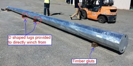
- At the site, arrange the base section on timber gluts (dunnage) so that it is in the vicinity of the already prepared foundation. Make sure the base section is secure and the slip joint end is clear of the ground and supporting timber gluts.
- Only one slip joint at a time should be assembled starting from the base of the pole.
- After reviewing the drawings and the pole sections, orient and sling the next pole section on to the base section as far as practical, maintaining true alignment of sections when viewed from the end and the side of the loosely assembled sections. The fold lines of the 12-sided pole sections should align closely when correctly aligned.
- Assemble the joining equipment between the D type jacking brackets at the slip joint.
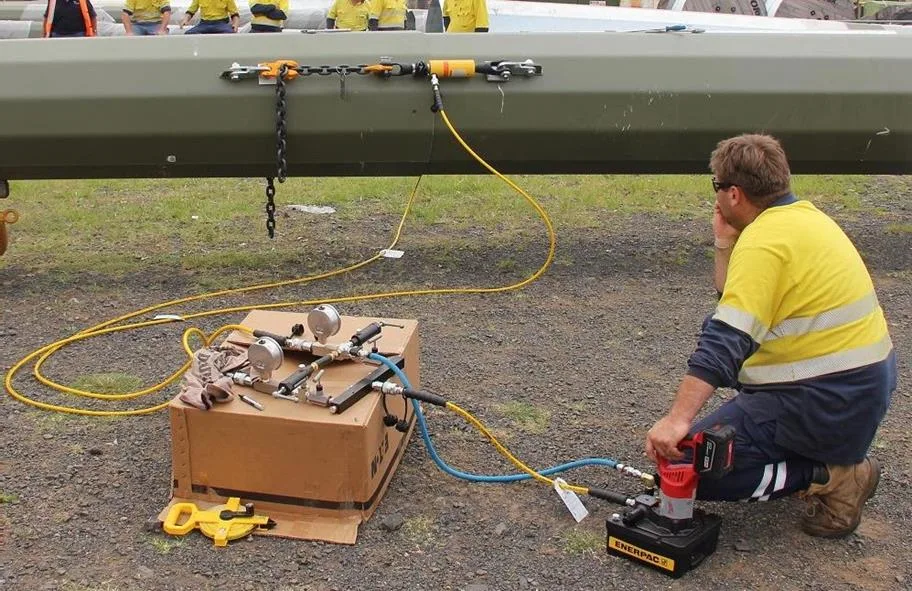
- The hydraulic equipment and cylinders should apply equal force to each side of the joint. Apply at least the minimum jacking force and check the slip length achieved. If it is past the marked design slip distance and the mating sections appear relatively tight fitting, then assembly is complete. Otherwise continue applying the jacking force up to the maximum and/or until the design slip distance is achieved.
- Contact International Utility Poles if the minimum slip distance is not achieved after the maximum jacking force has been applied.
- Assemble the next pole section as described above until the pole has been fully assembled.
Vertical Slip Joint Assembly
- Refer to pole approval drawings for minimum and maximum assembly forces to be applied to the slip joint.
- Please note that the jacking forces shown on the manufacture drawings is the total compressive force required to be applied at that joint for horizontal assembly. If vertical assembly is carried out then the total vertical compression force required to be applied, may be reduced by the weight of pole sections (in kN) above the joint being compressed. In this way, for vertical assembly, the total hydraulic compression force to be applied at joint can be less that that shown on the approval drawings.
- The method below utilises two hydraulic cylinders to compress the slip joints of the pole. For large poles, four hydraulic cylinders may be required (depending on the hydraulic cylinder capacity).
- The pair of bolt on D type jacking brackets are rated at either a 100kN or 150kN working load. These jacking brackets are multipurpose and a pair of them can be used to lift individual pole sections for a vertical pole assembly.
- Attach accessories, brackets, cross arms etc. to the pole section as deemed satisfactory according to a relevant safe work method statement prepared for the pole section erection at site.
- If there are earth wire arms at the top of the pole, the pole top section may be lifted from under the through vang plates (used to connect the arms) passing through the pole shaft, close to the pole section shaft.
- Any aids to assist with aligning the pole sections such as ropes can be attached to the D type jacking brackets at the bottom of the section.
- Jacking of the pole sections may be carried out after each pole section is added or else after all of the pole sections have been assembled. Jacking of the slip joints of the pole should commence from the lowermost slip joint.
- Refer to the previous section for general hydraulic slip joint assembly key points.
- Refer to the last section for fixing the base plate mounted base section to the foundation anchor bolts.
Erecting a fully Assembled Pole
- Attach accessories, brackets, cross arms etc. to the pole section as deemed satisfactory according to the safe work method statement prepared for the pole erection at site.
- As a safety measure, before lifting the pole, attach two suitably rated hand winches with wire ropes or chains between the uppermost and lowermost sets of the D type jacking brackets, located on both sides of the pole. The wire ropes (or chains) attached to these should be taut, so that pole sections are unable to separate in the unlikely event that pole sections have not been joined with a satisfactory jacking force. A correctly jacked section will not separate on lifting, but this safety measure should always be employed.
- A lifting sling may be choked around the pole below a suitable fitting assembled on the pole (for example a bolted on cross arm), or the two hand winches with wire ropes/chains may be shackled to the lifting sling to prevent the lifting sling sliding up the tapered pole. The choked sling should be positioned at least two thirds of the distance up from the base of the pole.
- All lifting equipment must be checked to ensure it is serviceable and adequate for the weight of the pole being lifted.
- Carefully raise the pole to its full height and manoeuvre it onto the foundation bolts.
Keep well clear of the base of the pole while it is being lifted.
Fixing the Pole/Pole Base Section to the Foundation Anchor Bolts
- The lifting crane is used to both hold and position the assembled pole or pole base section while it is levelled and the anchor bolts are tightened down.
- Prepare 4 nuts beforehand, to be used for levelling the pole. Lower the 4 nuts which are at 90 degrees apart to each other, so that they are 10mm lower than the rest of the nuts. Check that these 4 nuts are level.
- Carefully raise the assembled pole or pole base section to its full height and manoeuvre it onto the foundation bolts. Keep well clear of the base of the pole while it is being lifted.
- Place the pole on the 4 washers first and screw on the 4 corresponding top nuts to the 4 raised nuts underneath the base plate. Snug tighten down the 4 top nuts in a diametrically opposite sequence. Snug tighten the 4 underside nuts also and then check the pole alignment. If good, continue to put the rest of the washers and top nuts on the anchor bolts. Bring the remaining nuts on the underside of the baseplate up tight against the baseplate. Snug tighten down all top nuts in a diametrically opposite sequence. Then snug tighten all underside nuts in a similar sequence. Recheck the top nuts. Now apply the lock nuts to all foundation bolts snug tightening in a diametrically opposite sequence.
- Approximate bolt torque values for a snug tight condition are,
- M16 = 73Nm or 54lbft.
- M20 = 143Nm or 106lbft.
- M24 = 248Nm or 183lbft.
- M30 = 491Nm or 362lbft.
- M36 = 864Nm or 637lbft.
- M39 = 1115Nm or 820lbft.
- M42 = 1378Nm or 1020lbft.
- M45 = 1700Nm or 1254lbft.
- M48 = 2064Nm or 1520lbft.
- M56 = 2950Nm or 2176lbft.
- M64 = 3984Nm or 2938lbft.
- Remove the lifting sling from the pole or base section.
- Erection is complete.
- Should further clarification or assistance with understanding the assembly method be required, please contact International Utility Poles.