Light Pole Assembly and Installation Guide TP-006
Download PDFWarning
The purpose of this technical guide is to provide a guide to actions necessary to ensure that steel light pole sections are joined, assembled and installed in compliance with the applicable design standards. Suitably experienced and qualified personnel should be used for the assembly and installation of light poles. Should the user be unsure on the guidance provided in this document, please contact International Utility Poles. It is the responsibility of the installer to ensure that pole installation practices are sound and are acceptable to the appropriate government agencies and occupational health and safety requirements. This is a guide only and International Utility Poles does not accept any liability should any adverse action occur from the use of this guide.
Pole Assembly Introduction
Light poles are made up of tapered sections which lock together by a friction fit process known as slip joining. At a slip joint, the smaller diameter end is inserted into the larger diameter upper section. The overlap distance achieved is the ‘slip length’.
Preparation
- Generally, the pole assembly should be carried out in close vicinity to the prepared foundation.
- Check that all the relevant pole drawings are at hand, showing section lengths, diameters and identification markings.
- Confirm that the pole section components have been identified correctly.
Equipment for Assembly
All equipment must be suitably rated for its function and the load to be applied. The equipment in pole assembly is to be used for pulling and is required to have a minimum factor of safety of 2.0, whereas the rated Working Load Limit (WLL) for the items below is based on a much higher factor of safety required for lifting. It is up to the experienced professional operator to determine the appropriate factor of safety applicable and the appropriate WLL rating of the equipment required for the application and for the forces involved.
- For pole base section weights < 0.5 tonne; the Slip Joint assembly force required is 2 tonne.
- For pole base section weights > 0.5 tonne to < 1.0 tonne; the Slip Joint assembly force required is 5 tonne.
- For pole base section weights > 1.0 tonne to < 2.5 tonne; the Slip Joint assembly force required is 10 tonne.
- For pole base section weights > 2.5 tonne; seek advice from International Utility Poles.
The pole assembly equipment involved is as follows;
- One or two suitably rated hand winches (Tirfor or chain hoist winch) or hydraulic cylinders, with the appropriate length of wire rope or chain. The winch rating is to be appropriate for the weight of the pole base section being assembled as noted above.
- A safety rope (hand winch may be used or lifting sling to suit equipment being used and the pole length).
- Hand winch pulling frame or frames if a central single winch is used.
- Heavy bar or striker plate with centre lug for central single winch.
- Two or more round slings to suit the assembly and erection method adopted.
- Sledge hammer and nylon hammer, or steel club hammer with wooden block.
- Tape measure and marking pen.
- Timber bearers/packers. One large diameter steel pipe or roller for assembling larger heavier pole sections of an approximate weight of 1.0 tonne and above.
Main Shaft Assembly
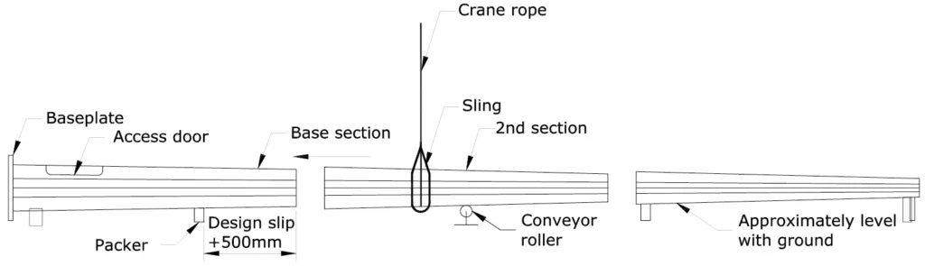
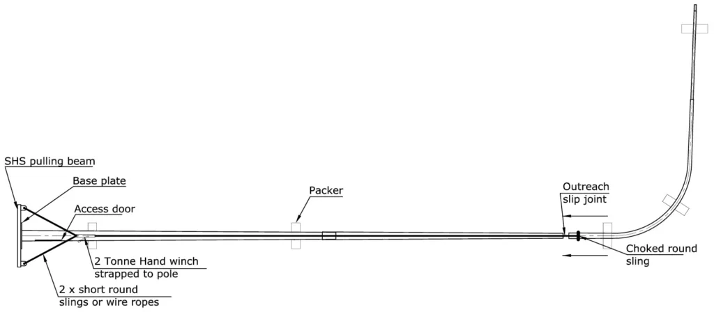
Arrange the sections on to timber packing so that the underside of the pole sections are relatively horizontal. Ensure the height of the timber packing is compatible between sections and provides adequate ground clearance. Check that the position of the timber bearer at the top end of the base section is approximately 500mm back from the design slip joint position, to allow for achieving the nominal slip length plus some additional overlap (Refer to Figure 1).
Wedge the base section to prevent pole rotation. Ensure that the base section is correctly aligned in relation to the door opening and for the outreach orientation (refer to Figure 1).
Next mark the nominated slip length (as shown on the relevant pole drawing, which is at least 1.5 times the internal diameter across flats of the female end of the joint) and an additional mark 200mm past the nominated slip length.
When assembling the next section up from the base, for pole section weights of 1.5 tonne or more, it is recommended that a single pipe or large roller be used in place of the timber bearers, to reduce friction in the slip joining process.
Sling the second section for assembly at its centre of gravity and engage the sections as far on as can be achieved with the crane, making sure that near perfect alignment is maintained. Only one section at a time is to be joined starting from the base section. For octagonal street light poles check that the seam welds are aligned with one another for the straight part of the pole (this may not apply for the top section to outreach slip joint).
Under strict supervision of an experienced operator, join the two sections together by applying a compressive force along the central axis of the two sections. Ensure that telescoping of the sections proceeds evenly at the centre of the pole and that no misalignment of the sections or the corner bend lines of the sections occurs.
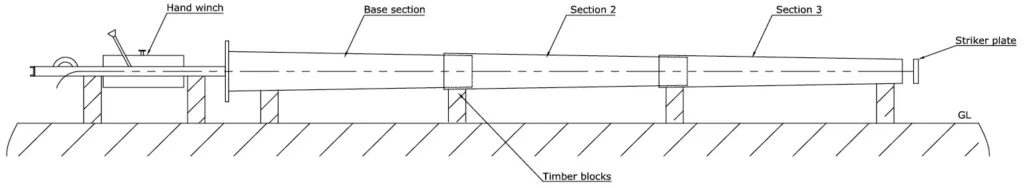
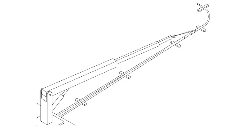
The recommended method utilises a hand winch with the appropriate steel wire rope, a pulling frame at the base end and a suitable striker plate or bar at the top end of the sections being joined (see Figure 2). It is best if the resultant compressive force is applied coincident with the pole axis.
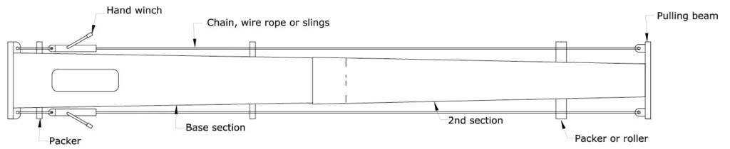
Gradually increase the compressive force to a maximum load of 2 tonne, 5 tonne or 10 tonne as applicable for the pole product. The 10 tonne compressive force may be applied by a single winch or via a dual winch arrangement (see Figure 3).
At the same time, the external surface of the slip joint can be hammered around the pole faces with a nylon hammer or steel club hammer via a wooden block, to assist the joint to achieve its full overlap (care needs be taken to ensure the pole’s galvanising is not damaged).
Apply the full applicable compressive force (as noted above for the base section weight), even if the design slip length is achieved at a much lower force. Apply the full force until the slip joint will close up no further. If the pole begins to bow significantly then stop winching and release the load (this may occasionally occur with very slender street light poles). Release the compressive force once the joint will close up no further.
If less than the nominated slip length is achieved, then check that the minimum allowed constructed slip length of 1.35 times the internal diameter of the female section, has been achieved. In the unlikely event that the minimum slip length has not been achieved, contact International Utility Poles for further advice. If there are concerns in achieving the nominated slip lengths before assembly, please contact International Utility Poles prior to commencing the assembly of the slip joints.
Before removing the crane sling, pack up the newly assembled section to the required level ensuring that the packing is approximately 500mm plus design slip distance, clear of the end of the section where the next joint is to be made. Proceed in this manner until the straight part of the pole is fully assembled, keeping a careful check on alignment.
Additional Requirements for Mid-Hinged Pole Assembly
Smaller mid-hinged poles which have no slip joints, are supplied fully assembled.
Larger mid-hinged poles with slip joints required above and below the hinge, are supplied with the apron section and pole section directly below the hinge, assembled as a single piece (hinge pin is installed). The pole sections above and below the hinge portion can be assembled by the slip joining process as described above for light poles.
The counter balance weight is located inside the pole apron and will normally be installed at the factory. If a counter balance has been supplied loose and not installed, please contact International Utility Poles for further instructions.
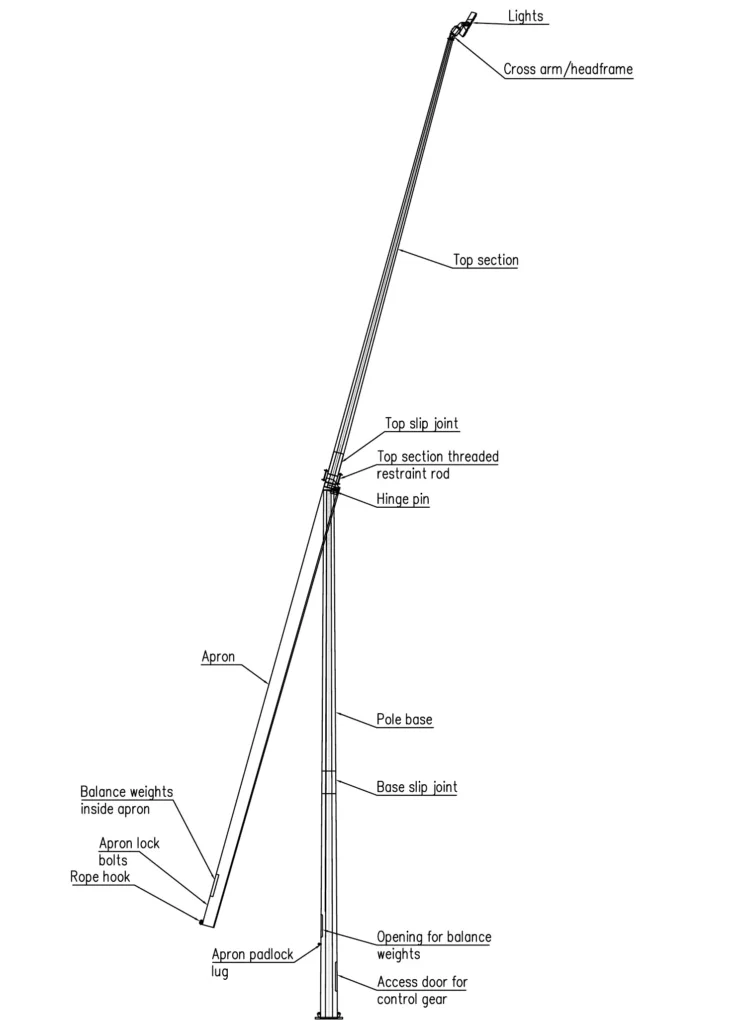
For poles with slip joints above the hinge (usually 18m mid-hinge poles and greater), these require each assembled slip joint to be positively restrained with threaded rods at the welded tabs supplied for that purpose (see Figure 4). The threaded rods, nuts and washers required are supplied with the pole sections. The threaded rods should be installed snug tight.
Regarding the securing of the headframe, it is important that the bolts on the cross arm spigot are securely tightened on to the pole top spigot so that no movement in the headframe will occur in the lowering process. The tightened bolts and a welded internal ring plate washer prevent the possibility of the head frame sliding off the top of the pole spigot.
Mid-hinged poles should be installed with all luminaires mounted on the cross arms or headframe before the pole is erected. In this way the pole should be correctly counter balanced in readiness for the lowering operation after installation.
It is best if the luminaires are wired up while the pole is on the ground. The draw wire and cables should have sufficient flexibility and additional length to bend through 180 degrees on lowering. It is recommended that a flexible conduit be installed over the cable length at the hinge which will bend around the hinge pin. This is to prevent any chafing of cables during the raising and lowering operations.
The apron of the mid-hinged pole must be locked in position against the pole shaft via the locking bolt and padlock positions provided on the pole before erecting the pole.
Following the above checks, the mid-hinged pole can be installed on the foundation hold down bolts as per the light pole installation procedure further below.
Refer to the separate mid-hinged pole operation guide before attempting to release the apron and lower the luminaires.
Assembly of Outreach to the Main Shaft of a Street Light Pole
For street light poles, either a modified winch method with choked sling or a crane truck lifting boom with a choked sling, can be used for joining the straight portion of the poles and a similar method is recommended to join the outreach to the assembled straight part of the pole (Refer Figures 5 & 6).
Before attaching the outreach, the straight part of the pole must be fully assembled. If the hydraulic pulling method using a crane truck lifting arm with a choked sling is used to slip join the outreach, the base end of the pole should be against a solid object, for example a kerb.
Check the outreach is oriented correctly in relation to the straight part of the pole. A soft sling is to be choked around the straight part of the outreach (so that it doesn’t slip down the outreach). Attach the free loop of the soft sling to a crane truck hydraulic lifting hook and pull the outreach onto the assembled straight portion of the pole (refer Figure 6).
Ensure that the hook of the hydraulic lifting arm on the crane truck is as close to the pole face as possible when applying the pulling force (but not so close that it rubs against the pole). This is to keep the load eccentricity to a minimum.
Apply up to a 2 tonne pulling force maximum. The truck operator can measure the pulling force applied.
Watch for any bowing of the pole during the application of the force and stop immediately if excessive bowing of the pole is visible. Check that the nominated slip length is achieved and failing that, that the minimum allowed constructed slip length has at least been achieved, as described above.
Pole Installation
Once assembly of the pole is complete, it is ready for installation.
Check that the lifting equipment to be used is in good condition and of adequate capacity for the weight of the pole being lifted.
Most light poles are installed on a hold down bolt foundation, however; some are in-ground mounted. Street light poles are installed on three common types of foundation arrangements; base plate, slip base and in-ground mounted. The street light pole slip base arrangement installation guide is detailed separately further below.
Base Plate Pole Installation
For a base plated pole installation, the hold down bolts are cast into a concrete foundation.
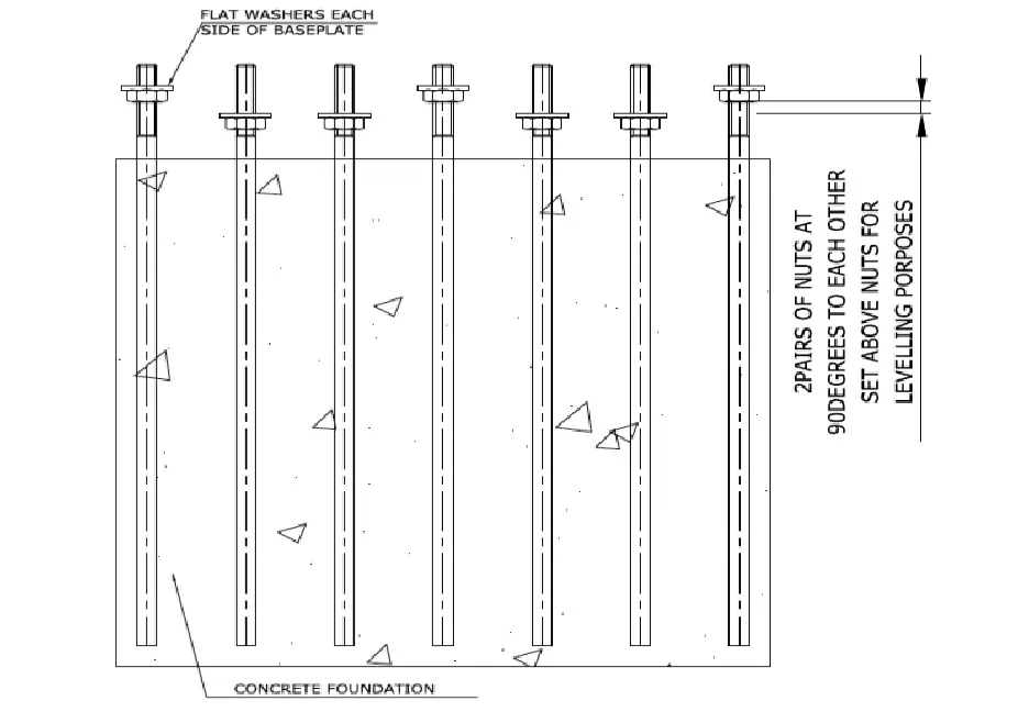
Once the foundation is adequately set, remove the top foundation bolt cage template and top nuts and washers, and check the nuts run freely on the threads. Lubricate the threads if necessary, to ensure they are free running.
Raise up 4 bottom nuts and their washers at 90 degrees to each other and using a spirit level, level the washers remaining that are resting on the bottom nuts (refer Figure 7). The base plate will sit on these washers (usually four bolts and washers).
Lifting the Pole
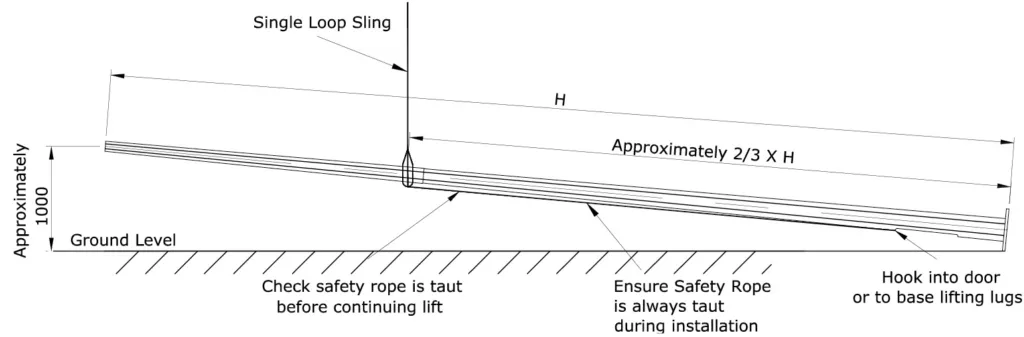
Attach a single loop round sling around the pole at approximately two thirds of the overall height. It is recommended that the sling is not choked around the pole (lifting operator can determine but it will easier to keep the safety rope taut if not choked). On the opposite side to the lifting side, attach a safety rope or chain from the sling and attach the other end to a hook, which is to be hooked into the access door of the pole for street light poles or in-ground mounted poles. If the pole is base plate mounted with lifting gussets, attach the hook to a lifting gusset and not to the door opening. The rope is to be of adequate capacity to take the full weight of the pole. This safety rope may be a wire rope or hand winch with wire rope or chain hoist with chain, or round sling. For safety it is very important that the safety rope is kept taut at all times.
Note that it is the supervisor’s responsibility to ensure that the safety rope remains taut and the hook remains in position at all times until the pole is permanently secured to the foundation.
The single loop sling around the pole should ideally be loose, to allow the sling to move up the pole as the pole is lifted, thereby keeping tension on the safety rope.
Begin lifting the pole. After lifting the top of the pole approximately 1m above the ground (base should still be supported on the ground), stop and check the arrangement. Ensure that the safety rope is still taut (refer Figure 8).
Continue lifting the pole ensuring that the safety rope remains taut at all times. Carefully place the pole on the foundation bolts. Do not release the load from the crane (safety rope is to still remain taut) until washers and nuts are placed on all threads and initially tightened.
Release the load from the lifting crane. The lifting sling should loosen, and the safety rope can be used to guide the lifting sling down the pole as the lifting crane cable is run down.
Remove lifting tackle.
Plumbing & Grouting
Plumb the pole using the adjusting nuts after checking the pole verticality in two directions at 90 degrees to one another. Do not remove the top nuts during the nut adjusting process.
For the best appearance of street light poles, it is more important to have the top of the vertical part of the pole in line with the base of the pole rather than just relying on having the base plate level. This is particularly relevant for the longer single outreach poles.
Tighten all nuts snug tight, firstly to the underside of the base plate and then tighten down the corresponding nuts above the base plate to achieve the desired plumbing of the pole.
The snug tightening of base plate anchor bolts is not an exact science and the bolt tension achieved can vary significantly depending on lubrication, thread tightness etc. For a lubricated galvanised anchor bolt, an approximation of the torque required to achieve the snug tight condition is given below. Note that this does not apply to slip base bolts. Refer to the slip base installation guide further below.
- M16 = 73Nm (54lbft)
- M20 = 143Nm (106lbft)
- M24 = 248Nm (183lbft)
- M30 = 491Nm (362lbft)
- M36 = 864Nm (637lbft)
All bolts should be rechecked to ensure they have had similar torque applied and are snug tight. Should there be any questions on this aspect, please contact International Utility Poles.
Fill the space between the base plate and the foundation with a non-shrink general purposeco nstruction grout as per the grout manufacturer’s instructions.
In-Ground Pole Installation
For in-ground pole and ground stub pole installations, refer to the relevant pole and/or specific foundation drawings for embedment depth required.
The diameter of the foundation hole should be at least 200mm larger than the diameter of the pole. Generally, foundations diameters are not to be less than 600mm in any soil type.
For cohesive soils (soils which have a clay component) the augured foundation hole will usually remain open without collapsing. Minimum 20MPa concrete backfill or a cement stabilised backfill or a granular backfill GAP20 (or similar) aggregate may be used to suit the soil conditions Granular backfill should be compacted in 150mm thick layers. The cement stabilised option involves mixing ordinary cement in a ratio of approximately 1:4 with the granular backfill and compacting in 150mm layers. Ideally a mechanical foot on a crane truck or similar can be used to compact the soil layers. Alternatively, a lump of solid timber or other hand compaction tool may be used to hand compact the soil in layers.
The concrete backfilled pole may require some temporary support while the concrete sets sufficiently, depending on the environmental conditions.
The bottom and top of the straight part of the pole should be plumbed as described in the plumbing section above, during the compaction process.
For cohesionless soils (usually sandy or some gravelly soils) the augured foundation hole may collapse without a liner being in place. If a sandy or gravelly soil foundation hole does not collapse, then backfilling can proceed as described above for cohesive soils.
In collapsing soils, a tube former (of PVC or steel) may be used. Generally concrete backfill (minimum 20MPa) is used to support the pole. If between the outside of the liner and the edge of the hole is open or collapsed, reinstate the soil integrity with granular backfill (GAP40 or similar) in compacted layers according to good practice.
Do not use the excavated soil for backfilling.
The International Utility Poles in-ground pole and ground stub depths are based on nominal good ground conditions. The onus on assessing the suitability of these embedment depths for a site and the responsibility of assessing and determining the applicable ground planting depth and backfill type for a site rests with the purchaser.
Slip Base Street Light Pole Installation & Maintenance
The slip base pole is to be fully assembled as described above.
The slip base street light pole is a frangible system that allows the pole to safely disconnect from its base connection on impact, at urban road traffic speeds. This lessens the likelihood of severe injuries resulting from the impact.
For the slip base poles to perform as designed, it is very important that the pole is installed correctly and maintained as follows (this installation guide follows the NZTA State Highway Design Manual and NZTA document No. TM-2007).
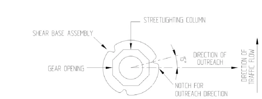
- Alignment of the slip base flange to the traffic flow should be as per Figure 9 below.
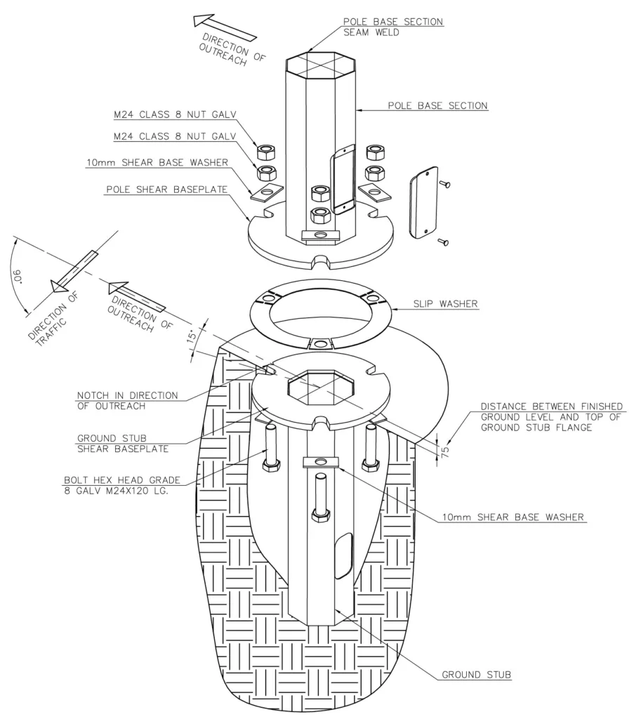
- An exploded view of an International Utility Poles slip base system is shown in Figure 11.
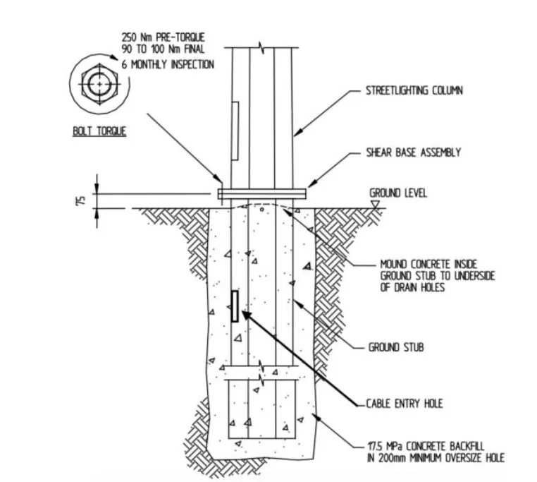
- The ground stub flange should be filled with concrete to the outside ground level using 17.5MPa concrete.
- If concrete is placed inside the ground stub it is important that the level should be just below the drainage holes near the top of the stub to aid water drainage. See Figure 10 below.
- Ensure that the top face of the ground stub is clean and free of dirt or any concrete from pouring.
- Ensure that the flange is level.
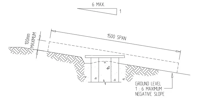
- Terrain in the vicinity of the slip base ground stub must be graded to allow a vehicle to pass over the stub without interference, and also to avoid the vehicle becoming airborne prior to impacting the pole.
- Generally, a negative slope of 1:6 should not be exceeded. The top of the ground stub flange should not protrude more than 75mm on horizontal ground conditions and on sloping ground conditions, not more than 100mm to highest part of the flange above the ground line, over a horizontal span of 1.5m – See Figures 9 and 10 above.
- The M24 x 110mm bolts must be greased with a suitable lubricant before torqueing.
Acceptable lubricants include Loctite Heavy Duty Anti-seize, Loctite Silver Grade Anti-seize, and Holts Lube. All parts of the thread must be coated with lubricant (For easy installation insert the bolts so that the nuts are facing upwards, refer Figure 12). - The M24 x 110mm bolts are to be tightened to 250Nm minimum torque, then slackened off and re-torqued to between 90Nm and 95Nm immediately or, at the very least, before the road is opened.
- If the bolts are left tighter than 100Nm, the slip base will not perform as required in the event of being struck. Correct alignment of all components should be checked at this stage. The use of locknuts is recommended.
- The slip base connection must be inspected every six months, or after significant weather events (severe wind speeds). Each bolt is to be removed, checked for condition (fatigue cracking, corrosion etc.) and then re-installed as per the above assembly notes. If there is any sign of fatigue damage to the bolt, the bolt must be replaced. Adequate pole support must be provided, or flange plate clamps used during the inspection process.